How to connect a receiver to the RX2SIM
The RX2SIM offers up to 8 proportional channels and works with all common transmitters on Windows, Mac OSX and Linux. It's a wireless simulator adapter. You don't need a trainer port in your transmitter, you simply need a receiver.
Make sure that your computer has an Internet connection when plugging in the RX2SIM the first time. The needed driver will be downloaded and installed automatically. Switch the RX2SIM into joystick mode (mode LED purple: game controller). Plug in the RX2SIM into a USB port of your computer and press the black knob at the side of the RX2SIM for a short time. Then the mode LED changes to purple.
We describe two receiver types.
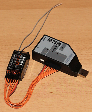
Connect the Futaba R6008HS with the delivered cables to your RX2SIM. This should work with all brands because the servo outputs are standardized.
Switch the input mode of the RX2SIM to 'Single Channels'. Press and hold the black knob until the input mode LED changes to the next type. Then you can release the black knob. Repeat this until you have reached the needed input mode.
The blue input mode LED will light up continuously if RX2SIM detects proper input signals from the receiver.
The input mode LED flashes if there is no valid input signal detected, which might be caused by selecting a wrong receiver type, transmitter turned off or improper operation of the receiver or transmitter.
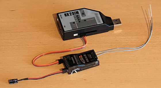
Switch the Futaba R7008SB into SBUS mode and connect it with one patch cable to the RX2SIM. Switch the input mode of the RX2SIM into 'SBUS' mode.
For some receivers, you need an capacitor to stabilize the cut-in voltage (330µF, 16V). For example Futaba high voltage receivers and JR receivers.
Without these capacitor, the receiver goes into low voltage error mode.
You don't need the capacitor for RX2SIMs that are delivered later than 8-25-2016.
- JR XG14 TX has 3 X.Bus modes, it needs to be Set on INH.
- When using a single Spektrum® remote satellite connected to RX2SIM: The bind sequence on the receiver must be initiated by RX2SIM.
- There are cases where its not necessary to update the firmware of the RX2SIM.
- In case you don’t use flight conditions/modes in reality, you dont need to configure them in the simulator either. Simply select the appropriate preset with the number keys 1, 2, 3 and 4.
- RX2SIM dongle mode: If the communication between the RX2SIM and the simulator does not work, your anti-virus may be blocking the communication via the COM port.
RX2SIM setup video:
An FMS compatible USB dongle is compatible with Windows as well as with Apple Mac OSX computers. It is however important to use an adapter that is compatible with your transmitter, especially for mini jack adapters as there are differences for mono or stereo signal routing.
- switch off your transmitter
- plug-in the usb cable
- Your transmitter should switch on automatically. Only if it does the transmitter is working in trainer mode.
The input monitor window displays the incoming remote control signals. Each function (collective pitch, rudder, aileron and elevator) should move a slider. If not, you have to change the channel in your transmitter to an other channel. For Futaba you can do this easily in the transmitters function menu. Your USB interface may be incompatible when you have tried all other channels without getting a response in the input channel overview.
Reduce the servo travel in your transmitter if the input monitor shows + or -100 before your sticks reach their physical end of travel. In our example we use a Futaba FX-30 and haven't changed any center or travel adjustment. You can disable any undefined or flickering channels.
Just click onto start calibration and follow the instructions and the simulator calibrates the output to -100 / 0 / +100.
The sticks shown at the bottom of the screen will guide you visually and display the requested input. Select your stick mode also in settings > output device.
Reduce the deadzone as much as possible. The sticks in neXt should not jitter. As a rule of thumb, the poorer the signal quality, the larger the deadzone. When using an RX2SIM, the value 0 is perfect. Set it to 1 or higher for other dongles.
FrOS: Create a new fixed-wing model in your transmitter. Connect the XSR-SIM USB dongle to the computer and bind it to your transmitter (D16, CH1-8, no telemetry).
OpenTX: Create a new fixed-wing model in your transmitter. Connect the XSR-SIM USB dongle to the computer and bind it to your transmitter (D16, CH1-8, no telemetry).
Now, lets proceed with the calibration. Just click on start calibration in settings > input device and follow the instructions.
The sticks shown at the bottom of the screen will guide you visually and display the requested input. The default transmitter mode is mode 2. You can customize the transmitter mode in the settings > input device tab and settings > output device.
We reduced the deadzone to 1.
For special functions such as autorotation or rescue, assign the switches in the transmitter to an output channel in the Mixer menu. Then you can assign them in the flight simulator to the desired function in the settings > input device > functions tab.
EdgeTX: Switch on the transmitter and create a new Airplane model. Engine: 1 Channel, Ailerons: 1 Channel, Tail: Traditional, Elevator: 1 Channel, Rudder: 1 Channel.
Plug the USB data cable into the switched-on transmitter. The remote control will now ask for the USB operating mode. Select the USB Joystick (HID) option.
Now, lets proceed with the calibration. Just click on start calibration in settings > input device and follow the instructions. The sticks shown at the bottom of the screen will guide you visually and display the requested input.
The default transmitter mode is mode 2. You can customize the transmitter mode in the settings > input device tab and settings > output device.
We reduced the deadzone to 1.
For special functions such as autorotation or rescue, assign the switches in the transmitter to an output channel in the Mixes menu. Press there the + symbol and select an available channel, e.g. CH5 for channel 5. Assign a slider or switch as Source. Press the + symbol again and create CH6 for channel 6. Assign a slider or switch as Source.
You can assign them in the flight simulator to the desired function in the settings > input device > functions tab.
OpenTX: Switch on the transmitter and create a new model for the flight simulator. Connect the FrSky Taranis/Horus to your computer with a simple USB cable and select the USB Joystick (HID) option. When the transmitter does not show this selection, activate this option with the Open TX Companion. No other USB adapter is needed.
Then select the Model Setup menu and set Internal RF Mode and External RF Mode to off. We don’t need to run the radio while its connected to our computer.
Now, lets proceed with the calibration. Just click on start calibration in settings > input device and follow the instructions. The sticks shown at the bottom of the screen will guide you visually and display the requested input.
The default transmitter mode is mode 2. You can customize the transmitter mode in the settings > input device tab and settings > output device.
We reduced the deadzone to 1.
For special functions such as autorotation or rescue, assign the switches in the transmitter to an output channel in the Mixer menu. Then you can assign them in the flight simulator to the desired function in the settings > input device > functions tab.
If the Transmitter is not recognized on a Windows 10 then Windows installed the wrong driver. The wrong driver is listed in the Windows Device Manager in the libusb-win32 devices category as BETTER_USB_HS. Right-click on BETTER_USB_HS and either return to the last working driver or let the appropriate driver be found on your computer. The appropriate driver is called USB Input Device. After successful installation, the remote control will be listed under the Human Input Devices category. Here's how to fix it: Video
FrOS: We cannot recommend this connection method under FrOS, as the signals arrive jerkily. Update the transmitter software to OpenTX or EdgeTX.
EdgeTX: Switch on the transmitter and create a new model for the flight simulator.
The simulator crashes when connecting the transmitter via ELRS Bluetooth if the ELRS module firmware is version 4.0.0 or lower. However, you can update the firmware to enable Bluetooth functionality..
- Open this page in Google Chrome: expresslrs.github.io/web-flasher.
- Turn on the transmitter and connect it to the computer using a USB cable.
- Select "USB Serial (VCP)" on the transmitter.
- In Web Flasher, select "Transmitter".
- Switch "Releases" to "Branches".
- Select "Firmware Version" and choose "master".
- Select the "Hardware Vendor" that matches your transmitter.
- Select the "Radio Frequency" that matches your transmitter.
- Select the "Hardware Target" that matches your transmitter and then click "Next".
- Set the "Flashing Method" according to your transmitter's instructions. "EdgeTX Passthrough" is common.
- Then follow the instructions.
With the latest firmware:
- Turn on the transmitter and access the "SYS" menu.
- Go to the "Apps" menu and launch "ExpressLRS".
- Set the "Packet Rate" to "100Hz Full" to prevent the Bluetooth receiver from being overloaded with too many identical data packets and causing intermittent lag.
- Select the [BLE Joystick] option.
- Search for the new device in your Bluetooth settings and pair it once. Afterward, the remote control will work wirelessly with the simulator via Bluetooth.
Now, lets proceed with the calibration. Just click on start calibration in settings > input device and follow the instructions. The sticks shown at the bottom of the screen will guide you visually and display the requested input.
The default transmitter mode is mode 2. You can customize the transmitter mode in the settings > input device tab and settings > output device.
We reduced the deadzone to 1.
- Switch on your transmitter.
- First of all, we define a new model. Select therefore the 'LNK' button.
- Then select the 'MODEL SEL.' menu and press 'RTN'.
- Select 'NEW' and press 'RTN'.
- Use the presets TYPE: AIRPLANE, WING: NORMAL, TAIL: NORMAL
- Now the new model is defined. You can rename it to 'neXt'.
- Switch off your transmitter and plug in the simulator cable.
- Your transmitter switches on automatically and shows in the display 'DSC / TRAINER CABLE IS DETECTED'.
- Select the 'LNK' button on your T14SG.
- Then select the 'FUNCTION' menu.
- There are already functions for Aileron, Elevator, Throttle and Rudder defined. Where they should be depends to the USB adapter. Please take a look at the two examples below. It's a good idea to disable the trim functions by defining '--'.
- Scroll down to page 2. The SE switch is already defined as GEAR.
- Then move to the 'VPP' row and assign there for example the 'SB' switch.
- Now You can check the output by pressing the 'U.Menu/Mon.' button on your transmitter (servo output).
Start the neXt simulator up, press esc and change to settings > input device tab. Now take a look at the input monitor window. Each function should come out on one channel or button. Now you can start the calibration and follow the instructions there.
These are two example setups for the FUNCTION menu of your transmitter.
SuperSimX All in One (mode 2: G4 G5 G6, 5 proportional channels, 3 button channels):
- 1 AIL, J1, -- (proportional channel)
- 2 ELE, J2, -- (proportional channel)
- 3 THR, J3, -- (proportional channel)
- 4 RUD, J3, -- (proportional channel)
- 5 AUX2, SE, -- (button)
- 6 AUX3, SB, -- (proportional channel)
- 7 AUX4, SA, -- (button)
- 8 AUX5, SD, -- (button)
FunFly Simulator (no switch, 4 proportional channels, 4 button channels):
- 1 AUX2 (not used)
- 2 AIL, J1, -- (proportional channel)
- 3 ELE, J2, -- (proportional channel)
- 4 AUX2 (not used)
- 5 AUX3, SB, -- (button)
- 6 THR, J3, -- (proportional channel)
- 7 RUD, J3, -- (proportional channel)
- 8 AUX4, SC, -- (button)
- Select the 'LNK' button on your T14SG.
- Then select the 'Function' menu.
- There are already functions for Aileron, Elevator, Throttle and Rudder that have been defined (channel 1, 2, 3 and 4). Don't touch them while they are working.
- Scroll down to channel 5 and change the function name to 'Auxiliary1'.
- Then move to the 'Control' row and assign there for example the 'SB' switch.
- Now You can check the output by pressing the 'U.Menu/Mon.' button on your transmitter (servo output).
Start the neXt simulator up, press esc and change to settings > input device tab. And select functions in the input device tab. Now take a look at the input monitor window. Move your 'SB' switch. If there is a button changing? Then you continue with the 'Button' workflow. If there responds a proportional channel to the switch? Then you continue with the 'Slider' workflow.
Button:
- Move the 'SB' switch to position off (motor on).
- Click assign in the autorotation line
- If you are using a button our your remote control, click on button, otherwise on switch.
- Move the 'SB' switch to position on (motor off).
- You will now be able to recognize what assigned button is controlled by the 'SB' switch in the autorotation line.
Slider:
- Move the 'SB' switch to position off (motor on).
- Click assign in the autorotation line and then onto slider or stick. Move the 'SB' switch to position on (motor off) and click next.
- You will now be able to recognize what assigned channel is controlled by the 'SB' switch in the autorotation line.
Complete!
Follow the GUI instructions for stick calibration. You can re-enter the button configuration screen later without having to re-run the stick calibration section.
- Select functions in the settings > input device tab.
- Start with throttle hold forward, idle up centered, dual rates forward and flaps gain centered.
- Click assign for flight condition 1, then on button and move idle up switch forward.
- Click assign for flight condition 2, then on button and center idle up switch.
- Click assign for flight condition 3, then on button and move idle up switch back (towards you).
- Click assign for flight condition 4, then on button and move dual rates switch down. Anytime this switch is down, flight mode 4 will take precedence over all other flight modes.
- Click assign for restart, then on button and press the red button.
- Click assign for landing gear, then on slider, turn knob fully clockwise and click next to complete.
- Click assign for autorotation, then on switch and move throttle hold switch back (towards you).
It is helpful when opening neXt to have the throttle hold active (switch down), idle up set to middle position, flight mode 4 active (dual rate mode switch down) in order for the program to detect proper switch positions.
Complete!
Turn on your MZ-32 and use a regular USB cable to connect it to your computer. No other USB adapter is needed. Select Joystick in the USB menu. Activate the option '0 - 100%'.
Mikado VBar Control
Use a regular USB cable, no other USB adapter is needed. Valerio Bottero shows it in a video
Mikado VBar Control Touch
Turn on your VBar Control Touch and use a regular USB cable to connect it to your computer. No other USB adapter is needed and don’t switch your radio to USB mode either. Raquel Bellot shows it in a video
There are cases where its not necessary to update the firmware of the RX2SIM. In case you don’t use flight conditions/modes in reality, you dont need to configure them in the simulator either. Simply select the appropriate preset with the number keys 1, 2, 3 and 4.
Switch on the transmitter and create a new model for the flight simulator. Connect the Jeti transmitter to your computer with a simple USB cable. Make sure it's in USB mode when you turn on the tx, and then in the settings (Screwdriver x Spanner) change Joystick mode to 0% ... +100%. And then do a calibration in the simulator.
Switch on the transmitter and create a new model for the flight simulator. Connect the Spektrum NX to your computer with a USB data cable.
Then select the USB Settings menu and set the Mode to Game Controller.
Now, lets proceed with the calibration. Just click on start calibration in settings > input device and follow the instructions. The sticks shown at the bottom of the screen will guide you visually and display the requested input.
The default transmitter mode is mode 2. You can customize the transmitter mode in the settings > input device tab and settings > output device.
We reduced the deadzone to 1.
If you would like use the neXt simulator with the Reflex XTR or Aerofly USB dongles on Apple Mac OSX computers, you will need to switch the Reflex dongle into joystick mode (see instructions below).
Now, lets proceed with the calibration. Just click on start calibration and follow the instructions.
The sticks shown at the bottom of the screen will guide you visually and display the requested input. The default transmitter mode is mode 2. You can customize the transmitter mode in the settings > input device tab and settings > output device.
We reduced the deadzone to 2.
Newer reflex XTR dongles have a ribbed button for switching the dongle into it's joystick mode.
- Connect the dongle to the USB port (if possible not to a USB hub and pull off other dongles).
- Press the button on the dongle and hold it down until one of the two LEDs will go out.
- Then you can release the button.
- Disconnect the dongle from the USB port, wait briefly and plug it in again.
- So you have switched the dongle into the next 4 possible modes.
- When the stick is in the joystick mode, the LED is flashing twice (mode 2).
Switching FlySky SM001 Operating Mode:
The FlySky USB simulator controller features several operating modes. The G3-G4.5 mode is compatible with neXt (D2 LED: Two flashes - one off).
- Put the transmitter into programming mode. To do this, hold the left stick in the bottom-left corner and plug the remote control into the computer's USB port.
- You can now cycle through the operating modes using the left button (Left Five-way Button). Press it briefly to switch to the next operating mode.
- Press the right button (Right Five-way Button) to exit the programming mode.
Depending on your control mode, you may need to hold the right stick in the top-right corner instead to enter programming mode on your SM001.